Introduction
In recent years, laser manufacturers have continued to push the limits of output characteristics — increasing power, pulse energy, and frequency capabilities.
For laser system integrators like OpTek Systems, this represents an opportunity to unlock new processing regimes. More powerful lasers open up new parameter spaces, enabling higher throughput and greater process flexibility.
However, when it comes to laser marking, higher laser power doesn’t automatically mean better results. Unlike drilling or cutting — where energy directly translates to material removal — marking is primarily about achieving the right contrast. Once a certain energy threshold is reached, increasing power further often leads to reduced mark quality rather than improvement.
Typically, a marking process begins with conservative parameters to establish a baseline quality. From there, the operator can scale up power or repetition rate and increase scan speed to maintain spot overlap. But as these adjustments are made, one of three scenarios usually occurs:
- Full Utilization – The system runs at maximum laser power and scanner speed while maintaining consistent mark contrast and definition. This is the ideal operating point, where throughput and quality are both optimized.
- System-Limited – The process becomes constrained by scanner speed or acceleration limits. Even with additional available laser power, the beam cannot move faster across the surface without exceeding the scanner’s physical limits.
- Increasing power no longer improves marking speed.
- Any further power increase risks surface damage or contrast loss.
- Quality Drop – As beam speed and power rise, the mark contrast begins to degrade due to overheating, excessive oxidation, or local surface modification. The result may be reduced visibility or inconsistent tone.
Beyond these trade-offs lies another route to higher productivity: splitting the laser beam spatially using a Spatial Light Modulator (SLM). This approach allows multiple marks to be created in parallel — dramatically increasing effective throughput without sacrificing contrast or exceeding the scanner’s limits.
Spatial Light Modulators
A Spatial Light Modulator (SLM) is an optical device that can dynamically shape and distribute laser light in real time. In marking systems, this means we can control not only the beam’s intensity but also its phaseand direction, allowing precise tailoring of how the laser interacts with the material surface.
Two main technologies are used:
- Phase Modulation (LCoS-based SLMs): Each pixel in the device alters the phase of the incoming wavefront. By programming specific phase patterns (often derived using Fourier optics), the laser beam can be diffracted into multiple smaller beamlets or reshaped into uniform top-hat profiles. This enables marking of several locations simultaneously or the creation of complex pattern geometries in a single exposure.
- Amplitude Modulation (DMD-based SLMs): Arrays of tilting micro-mirrors rapidly direct light either toward or away from the optical path. This effectively creates controllable “on-off” pixels, enabling high-speed beam multiplexing or masking for selective marking.
Because an SLM is fully programmable, one laser system can perform multiple marking modes without physical optics changes. Applications include:
- Parallel marking: Splitting a single laser beam into multiple spots to write several marks simultaneously — boosting throughput within the scanner’s mechanical limits.
- Adaptive power distribution: Dynamically balancing beam intensity between multiple foci to ensure uniform contrast across all marks.
- Shaped mark profiles: Adjusting the beam shape to achieve consistent colour tone or contrast regardless of surface curvature or material variation.
- Compensation and correction: Fine-tuning the energy pattern to correct for scanner field distortion or uneven marking response.
- Conceptually, the SLM functions like a dynamic hologram — reconstructing the desired beam shape or pattern at the workpiece with each laser pulse.
Case Study 1: Logo Marking
This case study demonstrates a specific example where SLM-based beam shaping significantly improved marking contrast and throughput in traditional text based marking on anodized aluminium.
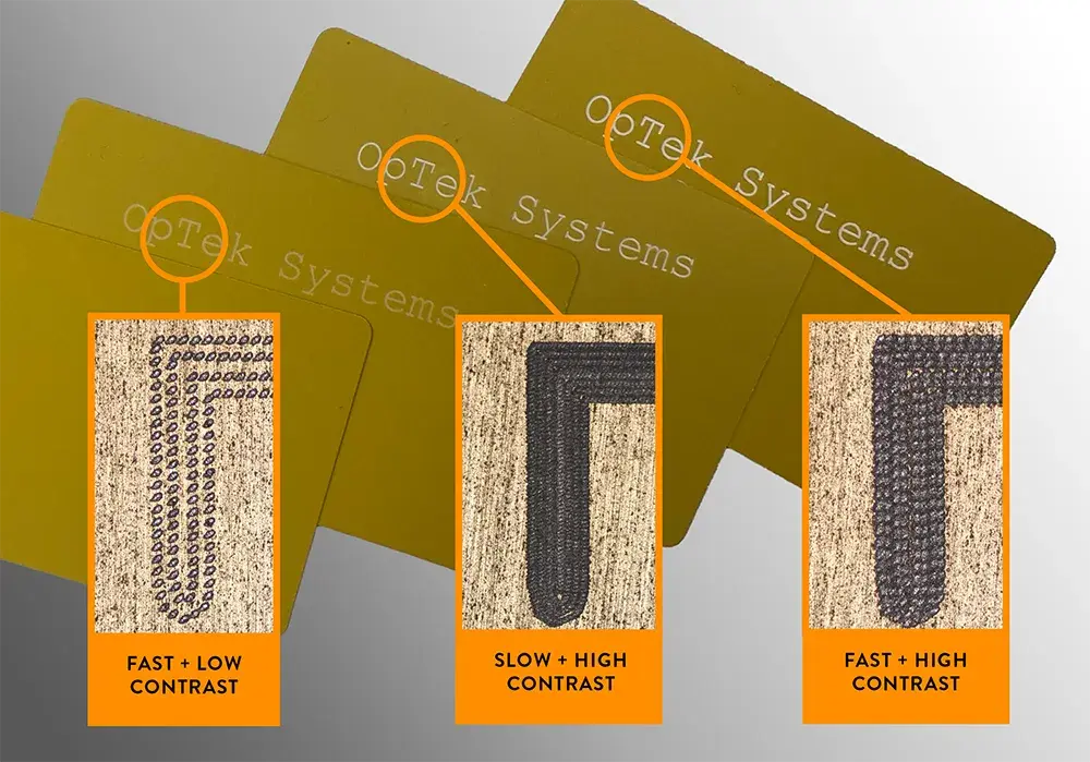
The left-hand exampleshows a fast mark completed in just 4.1 seconds. While throughput is high, the mark exhibits low visual contrast. Increasing the pulse energy alone does not improve the perceived contrast - it simply deepens the laser-etched features without enhancing appearance.
In the central example, the fill pattern density has been increased. This produces a much higher-contrast mark, but because the laser must address each spot individually, the total process time increases substantially to 16.4 seconds.
In the right-hand example, the same fill pattern as in the first test has been used, but with an SLM-enabled four-beam configuration. This approach delivers four times as many laser spots per pulse, reducing both the number of required pulses and the inter-spot movement time. The result is a high-contrast mark achieved at the same overall throughput as the original fast mark.
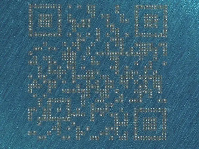
Case Study 2: QR Code Marking
This case study demonstrates a specific example where SLM-based beam shaping significantly improved marking contrast for a 29x29 sized QR code.
Original: Low Contrast QR Code

Low Magnification
High Magnification
Method 1: Multiply the number of pulses per spot
In the images below in order to try and achieve a higher contrast mark, the number of laser pulses per spot have been multiplied by 9.
Results:
- No contrast improvement
- 9x slower

Low Magnification
High Magnification
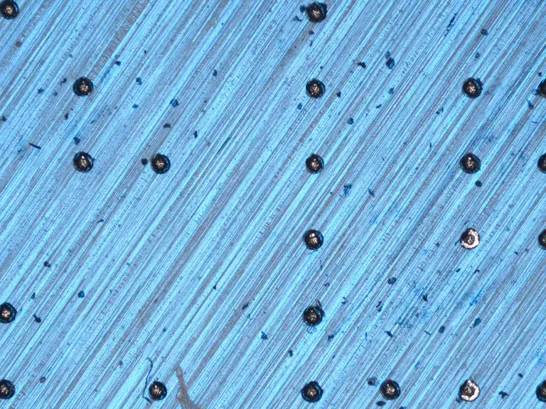
Method 2: Increasing Pulse Energy
In the images below in order to try and achieve a higher contrast mark, the amount of pulse energy per pulse has been multiplied by 9
Results:
- Speed maintained
- Slight contrast improvement
- Irregular spot size
Low Magnification
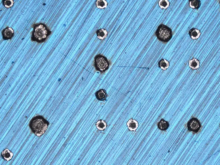
High Magnification
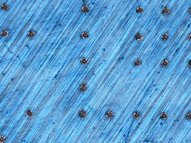
Method 3: Increase number of spots per pulse
By utilizing an SLM, we can produce a 3x3 grid of laser spots per single laser shot. This increases the contrast while maintaining throughput.
Results:
- Speed maintained
- Significant contrast improvement
- Increased scanning reliability
Low Magnification
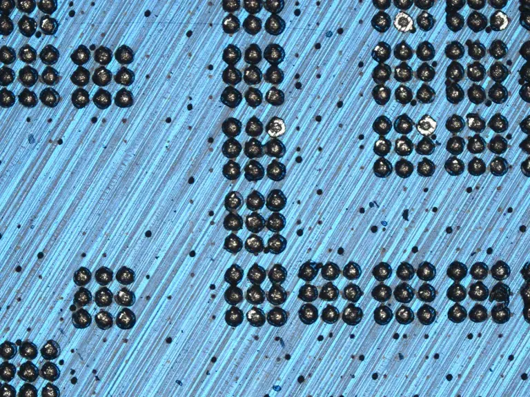
High Magnification
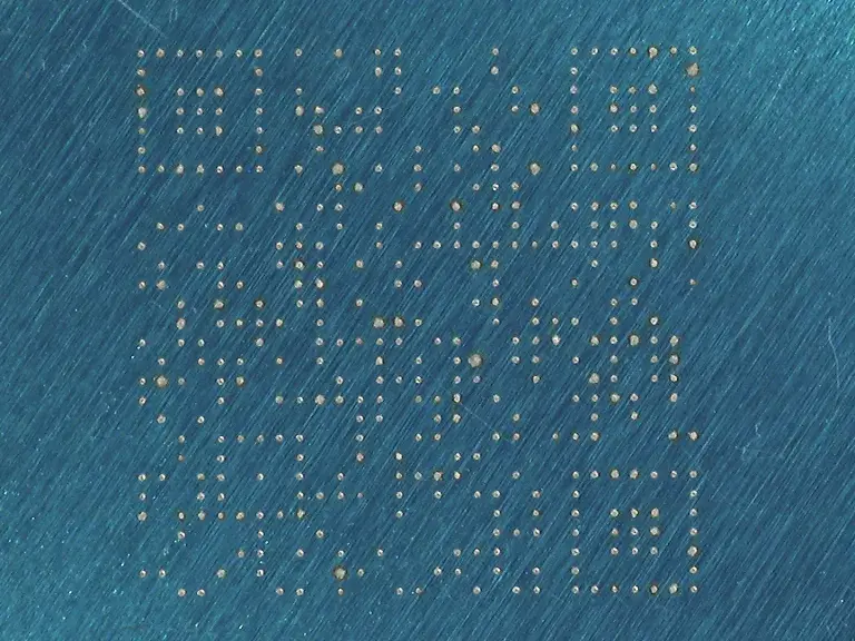
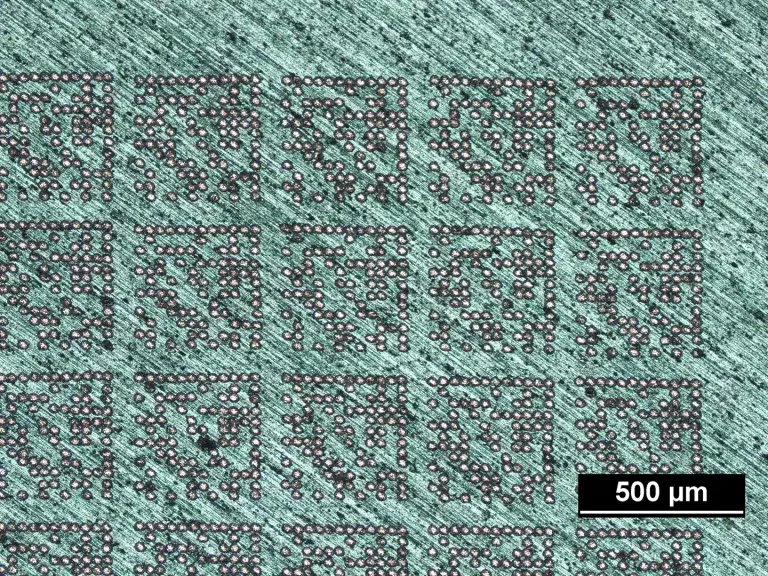
Case Study 3: Datamatrix Code Marking
This case study demonstrates a specific example where SLM-based beam shaping significantly improved marking thoughout for a small 12x12 sized datamatrix code, which would be used as a product identifier on a small component.
Single Beam Scanner Written
11 codes per second
Each spot is a single laser pulse, and the scanner has moved the laser between spots using a single beam arrangement.
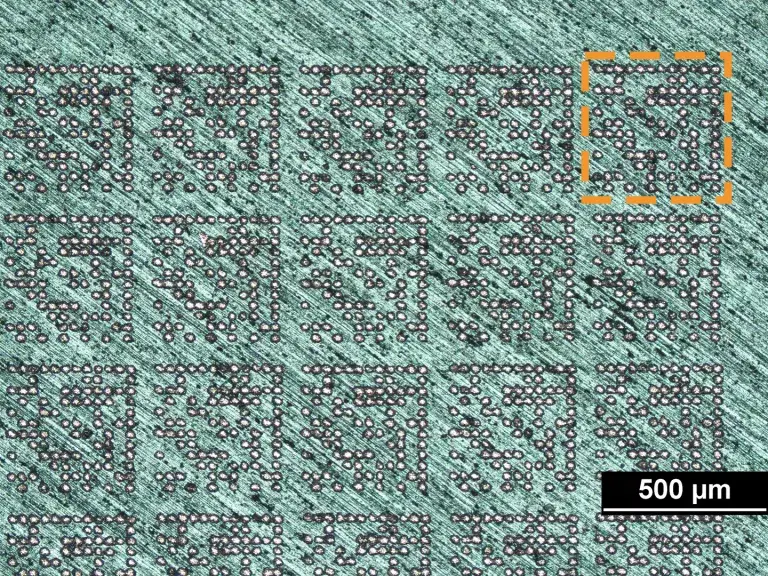
SLM Direct Stamp
920 codes per second
The SLM has been used to create a direct write datamatrix stamp. In other words, the SLM creates an array of 86 beamlets in the pattern indicated by the dashed orange square. This means that a data matrix can be written with a single laser shot.
Conclusions
As laser technology continues to evolve, the challenge in laser marking is no longer about generating sufficient power — it’s about using that power efficiently to maintain high contrast and consistent results.
Spatial Light Modulators provide a unique path forward by enabling parallel processing, adaptive control, and beam shaping— all without exceeding scanner limitations or compromising mark quality.
For system integrators like OpTek Systems, this translates to:
- Higher throughput without sacrificing contrast or clarity.
- Greater flexibilityto tailor marks for different materials and surface finishes.
- Future-proof system architecturescapable of adapting to new marking strategies through software rather than hardware changes.
In short, SLM-based multi-spot marking turns the traditional trade-off between speed and quality into a synergy — allowing both to be achieved simultaneously.